Since the beginning of the RepRap Project, people have fought jamming hotends. Me too. And even though there were some rays of hope lately, I didn’t build the “jack of all trades” (in german it’s die eierlegende Wollmilchsau, the “egg-laying woolly sow”) so far. But why? Time to condense what I learned from the may filament jams in the last six years…

…which was all about the plain vanilla, Open Hardware, modular types of Hotend. I’ve never invested in 1730, Prometheus, Flexion Extruder or the like and never used stuff like Ultimaker Print Cores, DyzEnd Pro or the Mosquito.
How complicated are those “plain vanilla” hot ends? Combining the different parts is quite easy, if you look for their interfaces. But: The devil is in the details. So I’ll try to break it down into individual chapters.
If you’re confused about the plethora of possible upgrades and spare parts on the WWW, maybe you’ll find this useful. If you’re searching for a checklist to get your printer going again, you might be better off just following the link to the Proto-pasta blog at the bottom. 😉
Heat sink
Let’s start top-down with the heatsink. It “interfaces” the filament coming from the extruder (the feeder or “cold end of the whole extrusion mechanism”) on one side and leads it to the heat break on the other. It also provides fixing to the carriage, but the main job of the heatsink is to keep your filament from becoming too soft (and sticky!) too early – by cooling down the heat break as much as possible. That’s it’s main job: Keeping the heatbreak cool!
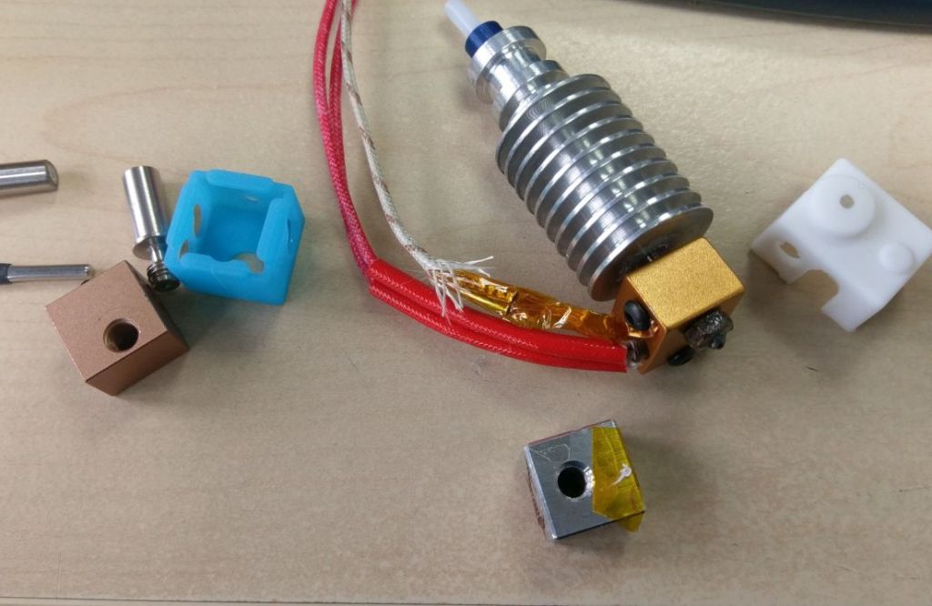
The Sumpod heat sink (depicted top left, just below) is screwed to the carriage via a pneumatic coupling at the top – something E3D recently took up again. The X5S‘ “Mk8” heat sink (top right) is screwed to the carriage via M3 screws. XCR BP6 and E3Dv5 (bottom left) as well as E3Dv6 (bottom right) heat sinks use the groovemount originating from Reifsnyder’s J-Head. (That’s the reason for some confusion of terms: Chinese vendors commonly refer to E3D-type hotends and heatsinks as “J-Heads”.)
While there are some dedicated “direct” feed heatsinks the most flexible ones will accept the filament via (at least a short piece of) Bowden tube. If you use one of those, you’re golden (if not, you are a bit more constrained when tinkering). Because you want to use “retraction” when printing, it is important to secure the Bowden coupling with a Collet Clip. Earlier designs use standard pneumatic connectors, but it has also come into fashion to embed them into the heat sink.
The (back then open source) Makerbot-Style Mk8 and derivatives, like the Micro Swiss ones (Anet A8 and Creality CR-10 drop-in replacement), as well as the E3Ds from the V6 on just let the PTFE Bowden tube pass into (or even through) the heat break, while older designs (Sumpod, E3Dv5) guide the filament through the aluminum. IMHO the latter is not a disaster – the critical part is the heat break. But letting the PTFE tube pass through the ‘sink will ease alterations or overhauls.


In my personal experience, the Sumpod heatsink was not that efficient, but the Mk8 (Mk10, …) ones were OK. The XCR BP6 “Hexagon” has one cooling fin less than the “v5”, meaning the v5 is superior. And the “v6” reings supreme. If your fan manages to buid up pressure. While I am writing this, my E3Dv5 heat sink is mounted, because the BP6 heat sink can’t keep the heatbreak cool enough. (Not even a custom-made Titanium one.)
If you go shopping for heat sinks in China, just note: To tell chinese v5 and v6 “J-Heads” apart, look at the original drawings. The v5 is in the old Wiki, the v6 in the current “dozuki” one.
I can publish them here unmodified, as they are permissively licensed. The older v5 version is 25 mm in diameter and 50 mm in length, while the v6 is 42.7 mm in length and 22.3 mm in diameter.


The interface for the heatbreak is where you have the most differences. The E3D v5 and the Mk8 use normal M6 threads, the E3D v6 uses M7 and the Hemera M4. The Mk10 or BP6 heatbreaks have smooth barrels and are fixed only with two grub screws. This means easier change (no rotation of the the heater block with all it’s cables required), but also less metal-on-metal surface contact. The thread makes spiral-, the smooth barrel makes line-contact with the heatsink. Maybe some of the “unsolvable” problems with PLA in all-metal hotends originate from the inadequate matching of heat break and heat sink threads? 🤔
Left pic: BP6 heatbreak (blank), v5 heatbreak (greased) and v5 heatsink. Right pic: Inserting the greased BP6 heatbreak – easier to change indeed, but not “cool enough” for my purposes.


BTW: Don’t mind the heatsink color. Black is good for passive cooling AKA natural convection – and on the hot end you need either forced air or water cooling. As soon as you use a fan, the color of the sink becomes negligible.
Fan and duct
If you’re printing ABS it might not matter to you, but printing PLA rather hot (i.e. at usually fast speed) and then slowing it down (at some feature of your print) can get you into trouble. The material takes the heat from the block down the nozzle and into the object – and the more your printer slows down the more heat will creep upwards. It is also the job of the fan to help preventing that.
You may want your fan to be silent, but as Thorinair commented here (31.05.2018), a fan that can build up a high static pressure (4 mmH2O or more) will give you a better safety margin over those silent Noctua (Original Prusa Mk3 and above) or Sunon HA40201V4-000U-999 your ears might prefer (those are usually rated around 2 mmH2O). Here a good air duct is important too, as you want the airflow to pass the cooling fins tightly, but without suffering too many losses. (And that’s the fan’s interface: The fan shroud or air duct.)
On the other hand: When printing ABS (or other warping-prone materials like “Arnitel“) you don’t want your heat sink fan to blow against the part you’re printing. So watch out for that!
Genuine, printed, E3Dv5 fan shroud (depicted top left), XCR metal bracket (top right), my own air duct without (bottom left) and with cardboard (bottom right) to keep ABS from warping.


Besides the static pressure versus airflow values of the fan (and obviously it’s size) you have to select the right voltage. If your controller board runs on more than 12V you may choose to use a 5V fan, as that nominal voltage might give you a better selection than e.g. 24V (if your controller board has a 5V rail, that is).
Heat break / throat
The heatbreak (or “throat”, as it’s called in the chinese-Makerbot-clone ecosystem) is the most critical part in your hotend. The sharper the transition beween the cold (filament feeding) part and the melt zone, the better your reliability and print quality. The smoother the inner surface of the heatbreak, the smaller the chance of softened PLA (or modified, “low temperature” PET like Innofil3D’s “EPR InnoPET”) sticking to it’s walls and ultimately stopping your print.
The latter is the ultimate disaster. Once PLA forms a sticky plug and corks your heatbreak, shit has already hit the fan and furthermore your Roomba is on it’s way…
It does not matter, how hard your extruder can push against it. I’ve tested some feeders by lifting weight and I can tell you: At some point they will be able to destroy the Bowden couplings, but not to push a “proper” hot end clog into the melt zone. However: Clogging hotends are not binary (on/off) and a properly powerful extruder (geared, dual drive wheel, very constraint filament path) will give you a fair margin in the transition area towards that point.
The easiest way around those clogs is to rule out the heatbreak at all. If your hotend lets the PTFE tube hit the nozzle, real nozzle clogs maybe more likely than a PLA clog in the heatbreak. My X5S came with a “straight through” throat, which worked like charm. E3D made the “Lite6” -specifically for ease of use- following the same principle. The manufacturer doesn’t have to care much about interior surface finish, as the only thing you’ll have to care about is, that the PTFE tube is cut off straight and really touches the nozzle inside the heater block (tutorial here). Left pic: X5S “Mk8”, PTFE-lined. Right pic: XCR BP6 heatbreaks, “high temperature” (full metal) on the left and “low temperature” (PTFE-lined / straight through) on the right.


It’s not that those PTFE-lined heatbreaks are completely foolproof – you can jam them up. And their main drawback is the temperature limit of ~245 °C, which effectively limits your material choices. But on the other hand: If you want to print ABS, Nylon, PC and so on, you’ll need to set up your printer for some different scenario (enclosure and powerful heatbed, but no part cooling fan) anyway. The PTFE will also limit the heat transfer to some degree, but if melt rate is your concern you might rather look at a “Volcano” setup with larger melt zone.
If you print mainly ABS on the other hand, full metal heatbreaks are much more likely to work flawlessly. It takes twice the heat PLA needs to get soft. So ABS is stiffer, keeps it’s shape better and is less sticky in the heatbreak. Fine. The full metal heat break serves as a thermal barrier, preventing the PTFE tube from seeing the hotend temperature here, so you can print as hot as your sensor or heater block tolerate.
But now: Back to the Eierlegende Wollmilchsau! The “universal heatbreak” is the part, where you really have to look for quality. A genuine E3D, Micro Swiss or RS Präzision product can save you a lot of trouble. And you’ll see below why. I’m not sure, if you really need Titanium [german post, but the charts are labelled in english], but if you process that stuff, chances are pretty high the surface finish will be decent.
You want your full metal heatbreak to stay as cool as possible at the top (obviously), so do yourself a favor and appy thermal grease. E3D seems to use Foshan satchets. “GD32” has a conductivity of 0.8 W/mK and “GD100” ~1.1 W/mK (their other product don’t seem to be available in those packages).
And while we are at using chemicals: Internal lubrication of the heat break (“seasoning with canola oil”) might be a last resort if nothing else helps. But keep in mind: Lubrication wears off quickly, can leave residue (carbonised plaque) in the nozzle and might torpedo your print’s adhesion to the build plate. Depicted below is stuff used as release agent for die casting. I originally asked for boron nitride in the foundry, but they did not have it. 😉


Apart from that: If your (already on hand or pack-of-five-from-china) heatbreak is too rough internally and the bore is slightly below 2 mm, you might be able to ream it, like I did here with a 2 mm H7 reamer and a fair amount of cutting oil – which might also be something containing PTFE.
If your heatbreak is drilled 2 mm or larger, you can only try polishing it. And please don’t do that with steel wool. Use the polishing compound contained in your Dremel tool set and pipe cleaners. Or simple rope. Either clamp the heatbreak into your cordless drill or move it back and forth (which has the advantage of polishing in the direction of filament travel).


Below on the left is depicted, what happens to an XCR steel heatbreak, if you use SWMBO’s steel sponge, wrapped around a drill. Top left: General surface quality on the outside (what the customer sees, is already not good…) Bottom left: Condition on delivery. Top right: Scars from the steel wool. Bottom right: Polishing coudn’t smooth it out any more than that.
The right picture shows the (ex-factory) surface of an RS Präzision Titanium heatbreak for comparison. Mirror polished, like you want it to be.


Update: Bimetallic heatbreaks are another take on it. 3DPrintBeginner has made a nice writeup here, while I was taking a sabbatical from 3D-printing in 2020. He even took measurements, comparing not Slice Engineering’s Mosquito or Copperhead, but a Trianglelab Bi-Metal Heat Break from Aliexpress to a regular E3D v6 style one. While the Mosquito is where the technology comes from, the Copperhead is their “construction kit” version to get simple upgrades into the market.
But in the meantime the chinese manufacturers have already made heavy use of bi metal heatbreaks. Trianglelab has thrown the Spider, Spiral Tower and Dragon Hotends onto the market. And they even have an E3D Hemera (“Matrix”) heatbreak available – while E3D themselves only use steel and titanium right now. The Mellow shop lists the Dragonfly, V6/Volcano Upgrade, NF TC-3A 2-in-1, NF-Crazy-A, NF Crazy plus and NF Zone hotends with bi-metal heat breaks. That started to get quite confusing in no time…
While the upper part of the heatbreak (the heatsink interface) is very specific, as described above, the lower part (the heater block interface) is usually an M6 thread of varying length.
Heater Block
The heater block transfers heat from the heater cartridge to the filament in the nozzle and holds the temperature sensor (in most cases a thermistor). It also stores a certain amount of heat, so the regulation can keep it constant. It keeps the whole hot side together, mostly by tightening the heatbreak thread against the nozzle thread.
A silicone sock helps not only to keep the block clean, but also protects against the part cooling fan accidentially cooling the block. (That may happen sporadically with certain geometries you print.) There are easily removeable sock designs and some, that require feed-through of cables.
For simplicity the nozzle as well as the hot side of the heatbreak have M6 outer threads, so the heater block just needs one M6 internal thread to connect them. Heater block thickness may vary, as well as nozzle- and heatbreak thread lengths, but in general most nozzles, blocks and heatbreaks can somehow be combined – as long as it’s all either Volcano or non-Volcano equipment.
I don’t have Volcano experience, but E3D’s blog post and this print speed calculator will give you some numbers on melt rates. The latter also compares the all-metal v6 to the PTFE-lined Lite6. (Dyze has an own one.)
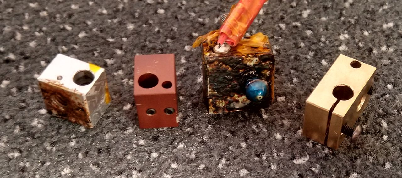
Below you see (from left to right) a fresh BP6 heater block and sock, the old E3D v5 aluminium heater block, a v6-sized block on a v5 heatsink and the (then fresh) sock for that block. Then (next pic) comes a plated copper heater block, properly resembling the v6 drawing, and it’s sock next to the block already depicted in the first picture (sock worn).


So what do you need to pay attention to, when choosing one of those?
- It has to generally fit your hotend (obviously).
- You don’t want the heater cartridge to be pinched by a grub screw. Instead you want a slotted block, that grips around it.
- You don’t want a fiddly “push-a-kapton-wrapped-glass-bead-into-a-cavity-and-then-shear-off-it’s-cables-with-the-screw-head” solution. Even if you mount it right, the thermistor might wobble while printing – giving you inconsistent readings. What you do want, is a cartridge thermistor.
- IMHO the logical order of positions is heater-nozzle-sensor (not placing the sensor next to the heater and the nozzle somewhere else).
- Mind the right sock version. The original (now: “pro”) version is overkill for genreal use – the current version, that does not cover the whole nozzle, is generally sufficient. If you buy in china, keep in mind that it’s a consumable good and you might need replenishment.
- The block material influences maximum printing temperature, heat transfer, capacity and weight. You might prefer copper over aluminum.
The nasty thing about the wobbely glass bead thermistor mentioned above is, that you might not see it, if you don’t use OctoPrint. On the left you see a glass thermistor being flung around (in the com.kabacon.octoremote App), on the right is a cartridge thermistor, observed via the normal web interface.


From left to right: E3Dv5 Block (grub screw for the heater, thermistor taped), XCR (cartridge thermistor, placed on the edge), Mk8 (like the v5, but larger), Trianglelab v6 clone (slotted, cartridge thermistor behind the nozzle).
…you might just consider a genuine “Block&Sock” pack from your local Distro, instead of ordering from China.
Nozzle
I won’t write about different Nozzle materials here. As with the Volcano heaters, I have no experience with them. At work I just printed one single part with a “Nozzle X” on a Prusa MK3S. E3D have made an overview here, then there is the The Olsson Ruby and Dyze’s tungsten carbide nozzle. But for me brass was fine so far. It also is forgiving enough to let almost any turning shop deliver decent products (and tungsten carbide seems to be the opposite of that).
Of course the nozzles have to be properly made, but they are in the hot part, meaning the material is already molten and can be pressed through the orifice without “ballooning”. If the orifice is thin enough. Have had one bad nozzle here, but that was ages ago. And Aluminium.
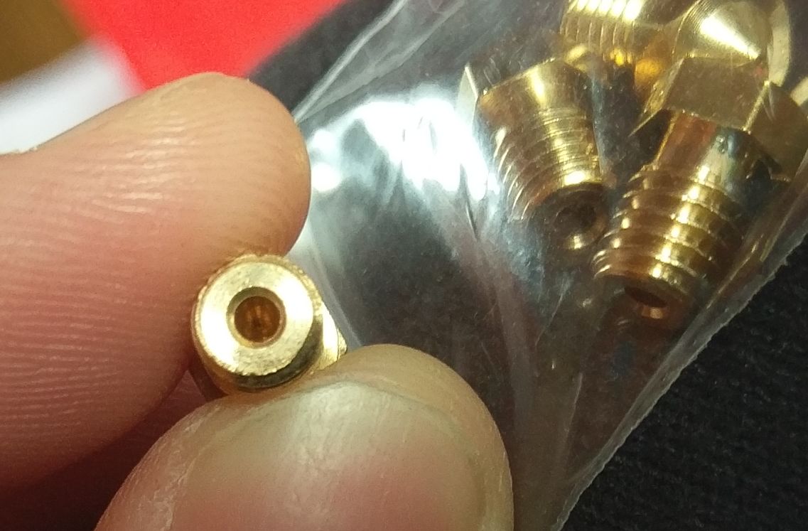
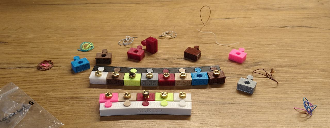
More relevant for the reliability of your hotend is the nozzle diameter. (My nozzle marker / sorter / holder can be found here on YouMagine and here on Libre3D.)
A small nozzle will act as a choke and restrict material flow. That leads to rising pressure and rising pressure might pile up and lead to one of those really bad clogs in your heatbreak, mentioned above. You can heat up your nozzle to ridiculous temps then (and watch totally liquid plastic drip out of the orifice), but the clog is located higher and can only be moved upwards. After re-inserting filament everything flows again. Until you re-start your print and let it run for a few minutes. Then it clogs again.
One of the immediate solutions for that situation is using a larger nozzle. The situation I thought to be cleared up here was only sorted out, as long as at least the 0.6 mm nozzle was mounted.
And if you follow Dyze’s recommendations on line width, that means at least 0.75 mm line width at 0.15 mm layer height. Which is bad news for many, many parts out there, that were constructed with “multiple of the 0.4 mm nozzle diameter” in mind – I know. So it’s not a solution for every situation. But by now you’ve read about the alternatives. 😉
Attribution
Thanks to Alex Dick for the best writeup about PLA jams in all-metal hotends so far! => https://www.proto-pasta.com/blogs/how-to/avoid-clogs-with-pla-composites-and-all-metal-hotends
TL;DNR
What you want to check, when trying to fix problems with your hot end (or if you’re looking for new components) is…
- You already did a series of cold pulls, did you? If there’s some debris blocking your orifice, nothing listed below will help…
- And did you rule out retraction? It is forbidden to retract out of the melt zone, when you use a full-metal heatbreak! Limit retraction to 2 mm and retraction speed to 40 mm/s.
- Is your hot end fan always on (or accidentially connected to the “part cooling” connector)?
- Is your fan blowing into the right direction? (Because it sucks at sucking air through the heat sink!)
- Are the fan specs (static pressure AND airflow) OK?
- Is your air duct any good?
- Is your heat sink generally up to the job? In an ideal world it’s bottom fin won’t be much above room temperature, even when printing at low speeds and layer heights (i.e. low volumetric flow rates).
- Is the PTFE tube in the heat sink tightly confined in it’s place and still OK? (Did it get damaged from the hobbed gears at the top or excessice heat at the bottom? Is it all the way in – and stays there?)
- Does your heat sink make ample contact with the heat break? (Screw the heatbreak into a warmed-up heat sink, like E3D suggests here!)
- Is the remaining space between ‘sink and ‘break filled with thermal grease?
- Is the interior surface finish of the heat break mirror-polished (if all-metal)? (If not: Consider getting a proper one!)
- Does your heater block have a sock / cotton wrap?
- Is your temperature constant when printing? (Or does the part cooler blow it ten degrees colder on layer two?) => Watch this with Pronterface or RepHost (if you don’t run OctoPrint anyway).
- Are you getting clogs, because you are printing too cold at the nozzle tip? A Temp-Tower will tell you!
- Are you getting clogs, because you are printing too hot for your feedrate and the heat still creeps up the sink? A Temp-Tower will tell you!
- Is (temporarily) using a larger nozzle diameter an option?
- Lubricate the interior of your hotend?
Update 2: E3D also have blogged what’s important to know about hotends from their point of view.
